Packet Tracer VLAN: Różnice pomiędzy wersjami
| (Nie pokazano 14 wersji utworzonych przez jednego użytkownika) | |||
| Linia 62: | Linia 62: | ||
Jak widać wszystkie porty należą do vlanu 1, czyli wszystkie podpięte hosty powinny się komunikować (oczywiście, jeśli zostały nadane adresy IP). | Jak widać wszystkie porty należą do vlanu 1, czyli wszystkie podpięte hosty powinny się komunikować (oczywiście, jeśli zostały nadane adresy IP). | ||
| + | |||
| + | Dodamy dwa vlany o numerach 2 i 3 oraz nadamy im nazwy VLAN2 i VLAN3. We wcześniejszym przykładzie vlan2 nazywa się VLAN1 a vlan3 VLAN2, przypominam, aby nie było pomyłki przy porównywaniu zrzutów. | ||
| + | |||
| + | <pre> | ||
| + | Switch#configure terminal | ||
| + | Enter configuration commands, one per line. End with CNTL/Z. | ||
| + | Switch(config)#vlan 2 | ||
| + | Switch(config-vlan)#name VLAN2 | ||
| + | Switch(config-vlan)#exit | ||
| + | Switch(config)#vlan 3 | ||
| + | Switch(config-vlan)#name VLAN3 | ||
| + | Switch(config)#exit | ||
| + | </pre> | ||
| + | |||
| + | Przypisujemy porty do vlanów. | ||
| + | |||
| + | <pre> | ||
| + | Switch(config)#interface fastethernet0/1 | ||
| + | Switch(config-if)#switchport mode access | ||
| + | Switch(config-if)#switchport access vlan 2 | ||
| + | Switch(config-if)#exit | ||
| + | Switch(config)#int fa3/1 | ||
| + | Switch(config-if)#switchport mode access | ||
| + | Switch(config-if)#switchport access vlan 2 | ||
| + | Switch(config-if)#int eth4/1 | ||
| + | Switch(config-if)#switchport mode access | ||
| + | Switch(config-if)#switchport access vlan 2 | ||
| + | Switch(config-if)#exit | ||
| + | Switch(config)#int fa1/1 | ||
| + | Switch(config-if)#switchport mode access | ||
| + | Switch(config-if)#switchport access vlan 3 | ||
| + | Switch(config-if)#exit | ||
| + | Switch(config)#int fa2/1 | ||
| + | Switch(config-if)#switchport mode access | ||
| + | Switch(config-if)#switchport access vlan 3 | ||
| + | Switch(config-if)#exit | ||
| + | </pre> | ||
| + | |||
| + | Jak widać komunikują się tylko hosty w ramach swoich vlanów. | ||
| + | |||
| + | [[Plik:vlan7.jpg]] | ||
| + | |||
| + | Możemy ponowić polecenie <code>show vlan</code> lub <code>show vlan id NR</code> albo <code>show vlan brief</code>, aby sprawdzić czy pojawiły się utworzone przez nas sieci wirtualne. | ||
| + | |||
| + | <pre> | ||
| + | Switch#show vlan brief | ||
| + | |||
| + | VLAN Name Status Ports | ||
| + | ---- -------------------------------- --------- ------------------------------- | ||
| + | 1 default active Eth5/1 | ||
| + | 2 VLAN2 active Fa0/1, Fa3/1, Eth4/1 | ||
| + | 3 VLAN3 active Fa1/1, Fa2/1 | ||
| + | 1002 fddi-default active | ||
| + | 1003 token-ring-default active | ||
| + | 1004 fddinet-default active | ||
| + | 1005 trnet-default active | ||
| + | Switch# | ||
| + | </pre> | ||
| + | |||
| + | ===Usuwanie interfejsów z sieci VLAN=== | ||
| + | |||
| + | Usuniemy interfejs Fa0/1 z vlanu 2, czyli tym samym usuniemy z tej sieci vlan Server0. | ||
| + | |||
| + | <pre> | ||
| + | Switch#conf t | ||
| + | Enter configuration commands, one per line. End with CNTL/Z. | ||
| + | Switch(config)#int fa0/1 | ||
| + | Switch(config-if)#no switchport access vlan 2 | ||
| + | </pre> | ||
| + | |||
| + | Sprawdzamy | ||
| + | |||
| + | <pre> | ||
| + | Switch#show vlan brief | ||
| + | |||
| + | VLAN Name Status Ports | ||
| + | ---- -------------------------------- --------- ------------------------------- | ||
| + | 1 default active Fa0/1, Eth5/1 | ||
| + | 2 VLAN2 active Fa3/1, Eth4/1 | ||
| + | 3 VLAN3 active Fa1/1, Fa2/1 | ||
| + | 1002 fddi-default active | ||
| + | 1003 token-ring-default active | ||
| + | 1004 fddinet-default active | ||
| + | 1005 trnet-default active | ||
| + | </pre> | ||
| + | |||
| + | ===Usuwanie sieci VLAN=== | ||
| + | |||
| + | <pre> | ||
| + | Switch(config)#no vlan 2 | ||
| + | </pre> | ||
| + | |||
| + | Sprawdzamy | ||
| + | |||
| + | <pre> | ||
| + | Switch#show vlan brief | ||
| + | |||
| + | VLAN Name Status Ports | ||
| + | ---- -------------------------------- --------- ------------------------------- | ||
| + | 1 default active Fa0/1, Eth5/1 | ||
| + | 3 VLAN3 active Fa1/1, Fa2/1 | ||
| + | 1002 fddi-default active | ||
| + | 1003 token-ring-default active | ||
| + | 1004 fddinet-default active | ||
| + | 1005 trnet-default active | ||
| + | </pre> | ||
[[Category:Cisco Packet Tracer]] | [[Category:Cisco Packet Tracer]] | ||
| + | |||
| + | [[Category:Sieci komputerowe]] | ||
Aktualna wersja na dzień 13:54, 17 mar 2014
W programie Packet Tracer stworzymy lokalne sieci wirtualne czyli VLANy.
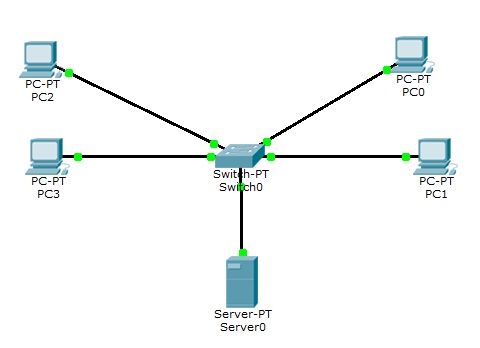
Mamy zwykłą sieć LAN. Komputery są odpowiednio skonfigurowane do pracy w sieci.
Konfigurowanie VLANów poprzez GUI Packet Tracer
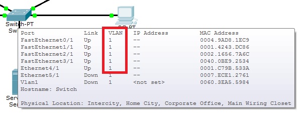
Jak widać na tablicy przełączania komputery się "widzą". Należą do jednego VLANu.
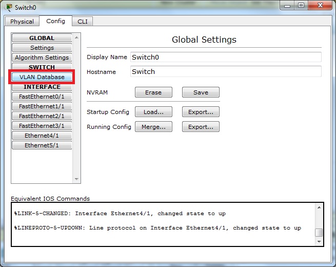
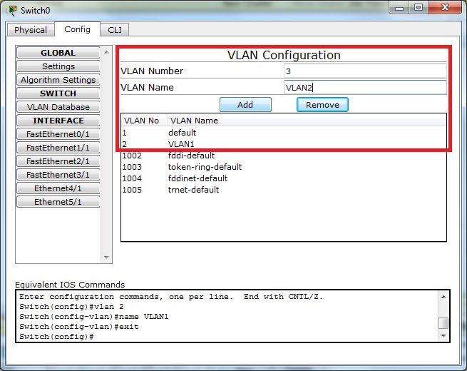
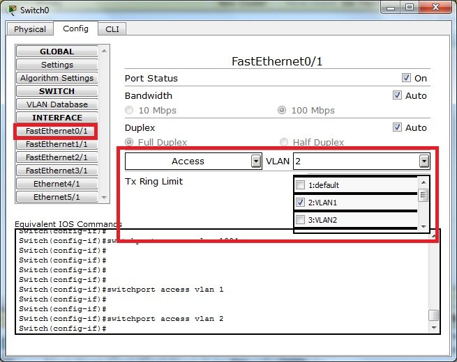
Na switchu dodajemy 2 sieci wirtualne, VLAN1 i VLAN2
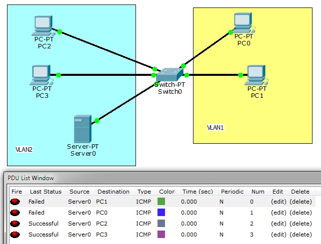
Przypisujemy porty switcha do odpowiednich VLANów
Jak widać komputery z różnych sieci wirtualnych nie widzą się. Pingi nie przechodzą.
Konfigurowanie VLANów poprzez CLI
Sprawdzamy jakie posiadamy VLANy na przełączniku. Służy do tego polecenie show vlan
Switch>enable
Switch#show vlan

VLAN Name                             Status    Ports
---- -------------------------------- --------- -------------------------------
1    default                          active    Fa0/1, Fa1/1, Fa2/1, Fa3/1
                                                Eth4/1, Eth5/1
1002 fddi-default                     act/unsup
1003 token-ring-default               act/unsup
1004 fddinet-default                  act/unsup
1005 trnet-default                    act/unsup

VLAN Type  SAID       MTU   Parent RingNo BridgeNo Stp  BrdgMode Trans1 Trans2
---- ----- ---------- ----- ------ ------ -------- ---- -------- ------ ------
1    enet  100001     1500  -      -      -        -    -        0      0
1002 fddi  101002     1500  -      -      -        -    -        0      0
1003 tr    101003     1500  -      -      -        -    -        0      0
1004 fdnet 101004     1500  -      -      -        ieee -        0      0
1005 trnet 101005     1500  -      -      -        ibm  -        0      0

Remote SPAN VLANs
------------------------------------------------------------------------------


Primary Secondary Type              Ports
------- --------- ----------------- ------------------------------------------
Switch#
Jak widać wszystkie porty należą do vlanu 1, czyli wszystkie podpięte hosty powinny się komunikować (oczywiście, jeśli zostały nadane adresy IP).
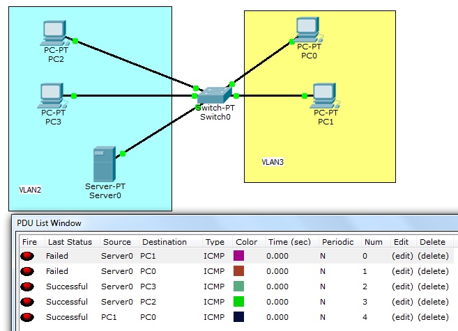
Dodamy dwa vlany o numerach 2 i 3 oraz nadamy im nazwy VLAN2 i VLAN3. We wcześniejszym przykładzie vlan2 nazywa się VLAN1 a vlan3 VLAN2, przypominam, aby nie było pomyłki przy porównywaniu zrzutów.
Switch#configure terminal
Enter configuration commands, one per line.  End with CNTL/Z.
Switch(config)#vlan 2
Switch(config-vlan)#name VLAN2
Switch(config-vlan)#exit
Switch(config)#vlan 3
Switch(config-vlan)#name VLAN3
Switch(config)#exit
Przypisujemy porty do vlanów.
Switch(config)#interface fastethernet0/1
Switch(config-if)#switchport mode access
Switch(config-if)#switchport access vlan 2
Switch(config-if)#exit
Switch(config)#int fa3/1
Switch(config-if)#switchport mode access
Switch(config-if)#switchport access vlan 2
Switch(config-if)#int eth4/1
Switch(config-if)#switchport mode access
Switch(config-if)#switchport access vlan 2
Switch(config-if)#exit
Switch(config)#int fa1/1
Switch(config-if)#switchport mode access
Switch(config-if)#switchport access vlan 3
Switch(config-if)#exit
Switch(config)#int fa2/1
Switch(config-if)#switchport mode access
Switch(config-if)#switchport access vlan 3
Switch(config-if)#exit
Jak widać komunikują się tylko hosty w ramach swoich vlanów.
Możemy ponowić polecenie show vlan lub show vlan id NR albo show vlan brief, aby sprawdzić czy pojawiły się utworzone przez nas sieci wirtualne.
Switch#show vlan brief

VLAN Name                             Status    Ports
---- -------------------------------- --------- -------------------------------
1    default                          active    Eth5/1
2    VLAN2                            active    Fa0/1, Fa3/1, Eth4/1
3    VLAN3                            active    Fa1/1, Fa2/1
1002 fddi-default                     active
1003 token-ring-default               active
1004 fddinet-default                  active
1005 trnet-default                    active
Switch#
Usuwanie interfejsów z sieci VLAN
Usuniemy interfejs Fa0/1 z vlanu 2, czyli tym samym usuniemy z tej sieci vlan Server0.
Switch#conf t
Enter configuration commands, one per line.  End with CNTL/Z.
Switch(config)#int fa0/1
Switch(config-if)#no switchport access vlan 2
Sprawdzamy
Switch#show vlan brief

VLAN Name                             Status    Ports
---- -------------------------------- --------- -------------------------------
1    default                          active    Fa0/1, Eth5/1
2    VLAN2                            active    Fa3/1, Eth4/1
3    VLAN3                            active    Fa1/1, Fa2/1
1002 fddi-default                     active
1003 token-ring-default               active
1004 fddinet-default                  active
1005 trnet-default                    active
Usuwanie sieci VLAN
Switch(config)#no vlan 2
Sprawdzamy
Switch#show vlan brief

VLAN Name                             Status    Ports
---- -------------------------------- --------- -------------------------------
1    default                          active    Fa0/1, Eth5/1
3    VLAN3                            active    Fa1/1, Fa2/1
1002 fddi-default                     active
1003 token-ring-default               active
1004 fddinet-default                  active
1005 trnet-default                    active
